Bench Grinder Tool Rests
July 2016
BACK
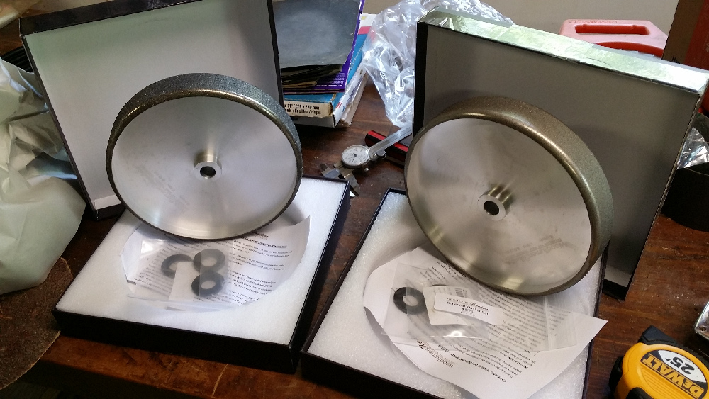
A few months ago, I bought a couple of Cubic Boron Nitride (CBN) wheels to sharpen lathe tools, knives, chisels and other edge tools ... it seemed like a great alternative to the traditional friable alumina wheels because they don't generate a lot of heat, they never need truing, they cut more consistently and have a much longer usable lifespan. However, I still wanted to keep my alumna wheels for other stuff (CBN clogs easily so you can't use them with mild steel or non-ferrous metals). Which meant I'd need another motor.
My dad came to the rescue, or so I thought, by giving me his slow speed grinder that was perfect for this application. However, he also gave me the Razor Sharp Edgemaking System that he had mounted on it.
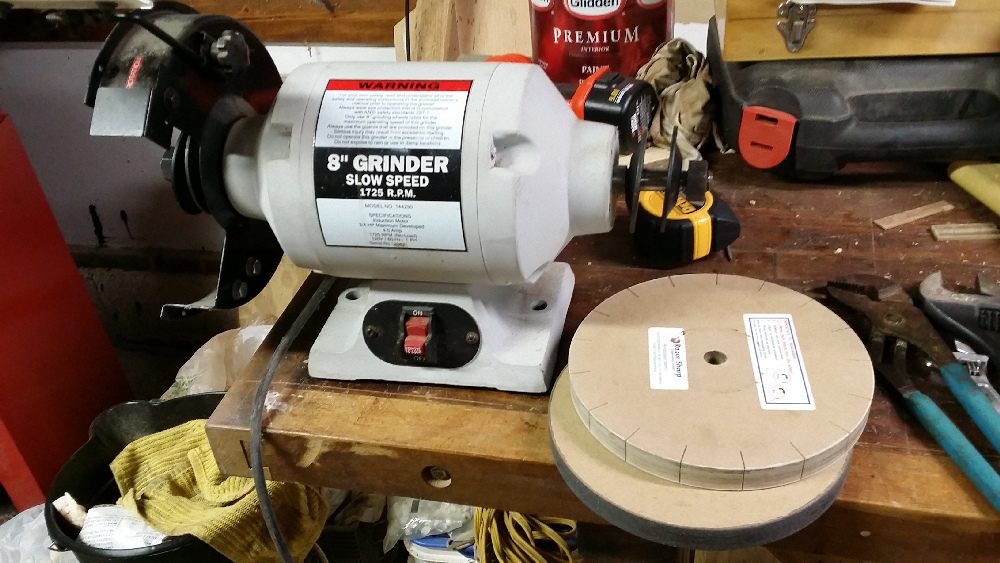
RSES is a very cool concept, comprised of a pair of paper composite wheels (not MDF exactly, it's similar in density but layered), one has a renewable coating of glue and emery powder (and charged with a beeswax lubricant), the other is a slotted wheel charged with tripoli polishing compound, also renewable. I made the mistake of trying them and was instantly hooked ... while the edge quality was not as refined as what I could get with Japanese waterstones, the process was so blindingly fast and easy it didn't make much sense to just stick these wheels in a drawer.
So... time to visit the new Harbor Freight store on Grand Opening Day armed with a 25% discount coupon ... and buy another motor. That brought the total to four, counting my old Craftsman utility motor (which mounts buffing wheels, flap sander, wire wheels, whatever).
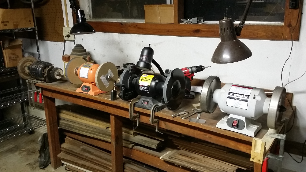
That pretty much filled up my sharpening station table. Overkill? Maybe ... some folks have a stack of stones, buffers, etc, and they swap them out on one motor, but that never made much sense unless you're just doing rough work ... because getting wheels balanced and true so that they cut accurately and don't vibrate can sometimes take a half hour or more, which means that once you have a grinder set up properly it's easier to not mess with it and just spend fifty bucks on another motor, assuming you have the space (which I kinda do, barely ... the space the two new motors took was where I set up my waterstones, but I guess I can just use the workbench which is at a better height for honing anyway).
There was one remaining problem. Unless you're one of those lucky folks who can drop $700 on an industrial Baldor grinder, most of the time when you buy a grinder you're gonna end up with a fairly reliable (if run-of-the-mill) motor but really awful tool rests. And by awful, I mean anything from crudely functional (say a cast iron rest with two adjustments ... in/out and angle) to practically unusable (flimsy stamped metal with no adjustments at all), and in nearly all cases the platform part of the rest is too small and uneven to hold a tool reliably, especially in those cases where you have to slide or roll the tool when sharpening. Here's a couple of examples...
_Crop_sm.jpg)
Since original equipment tool rests on most grinders are so legendarily bad, for some decades now there has been quite a brisk trade in after-market rests. But I was pretty much tapped out, budget-wise ... so buying two or three after-market Veritas rests at $60 a pop was out, even though they are beautifully made and definitely worth the money.
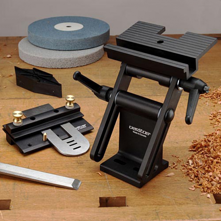
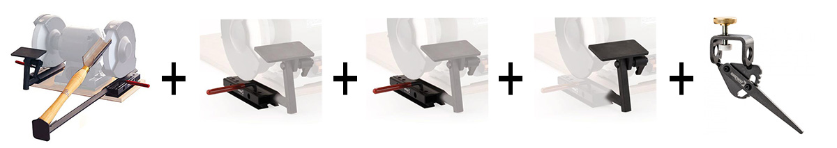
Besides, that would only give me a standard rest, I'd still have no consistent way of doing conical bevels on chisels and lathe tools, or compound bevels on bowl gouges. For that I'd need something like the Wolverine system ... let's see, four bases, two rests, a pocket rest and a compound jig... about $260 all together.
The obvious alternative was to make something. Aside from the time, the only real investment would be a few bits of hardware... some nuts, washers and all-thread. Lord knows there's enough scrap wood laying around here to cover everything else.
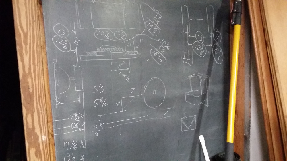
So after a week or two of checking out woodworking sites and YouTube videos looking for ideas to steal, and putting the pieces together in my mind while I was driving the car or pretending to be listening to my dear wife, I went down to the shop armed with a few rough sketches and started laying out the plans on my chalkboard.
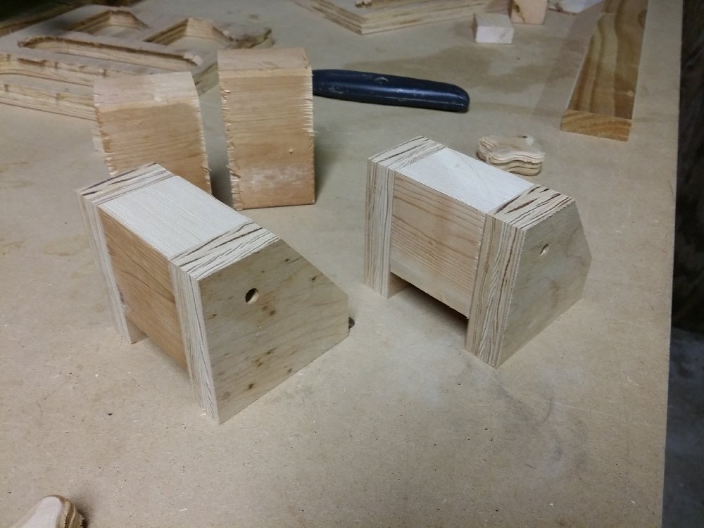
First thing was the base. I had settled on 1x2 lumber for the sliding arms, and after ripping and chamfering the arms, I began building up the base with scrap one-by, leaving recesses for the arms, centering them as best I could under each wheel. Sides and bottom were 1x4 and 1x8 pine, with 1/4" plywood covering the recesses.
_sm.jpg)
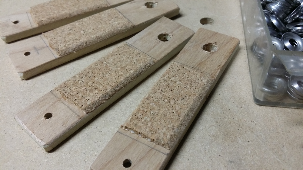
After a little more hand-planing for final adjustment of the arms they were all sliding smoothly in all four pockets. They would be held in place with some slightly springy hold-downs made of plywood and some cork sheet (with the edges beveled so they wouldn't catch).
The final step was to attach the motors to the bases with lag bolts. This was quite a milestone for yours truly because after nearly 40 years of woodworking, I think it might be the first time I've used a grinder that wasn't attached to the bench with C-clamps.
_sm.jpg)
Next came the tool rests.
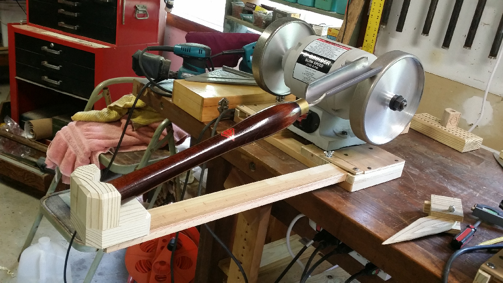
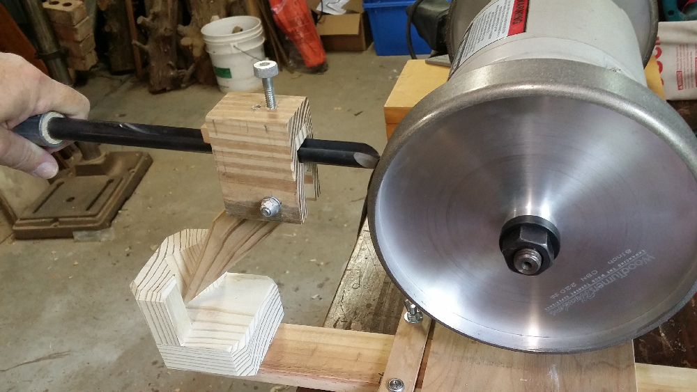
The easiest thing was the pocket arm so it got tackled first. It's basically two walls and a floor, in which you can rest the handle of a gouge with three points of contact so that it can rotate smoothly around its axis and create a conical bevel of a constant angle on the edge of the tool. Ordinarily the dimensions would not be critical, but since I would also be using the socket to support the pivot point on the compound jig it had to be constructed with the bottom of the pocket exactly four inches below the axis of the wheel.
The rest only extends seven inches when used with the compound jig, but it was mounted on a longer arm to accommodate other lathe tools, most of which have pretty imposing handles compared to chisels and carving tools. You set the handle of a gouge in the pocket and rotate it to get a nice even grind, or just hold it steady if it's a parting tool or flat chisel (see safety note at the end of this section).
Next up was the jig for my favorite and most-used lathe tool, the bowl gouge. Traditionally, they were sharpened with a conical grind but today most turners prefer a compound bevel (the so-called "Ellsworth" or "Irish" or "fingernail" grind) ... steep in front, shallow on the sides.
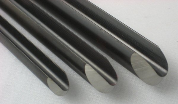
These can be sharpened by hand but it is tricky and inconsistent... you usually tend to remove more steel than you want, so it helps to have a guide that will allow you to match angles and remove just a few thousandths each time (that's important since you usually have to sharpen a lathe tool far more often than chisels or plane blades... your $80 gouge can get worn down to a nub in short order).
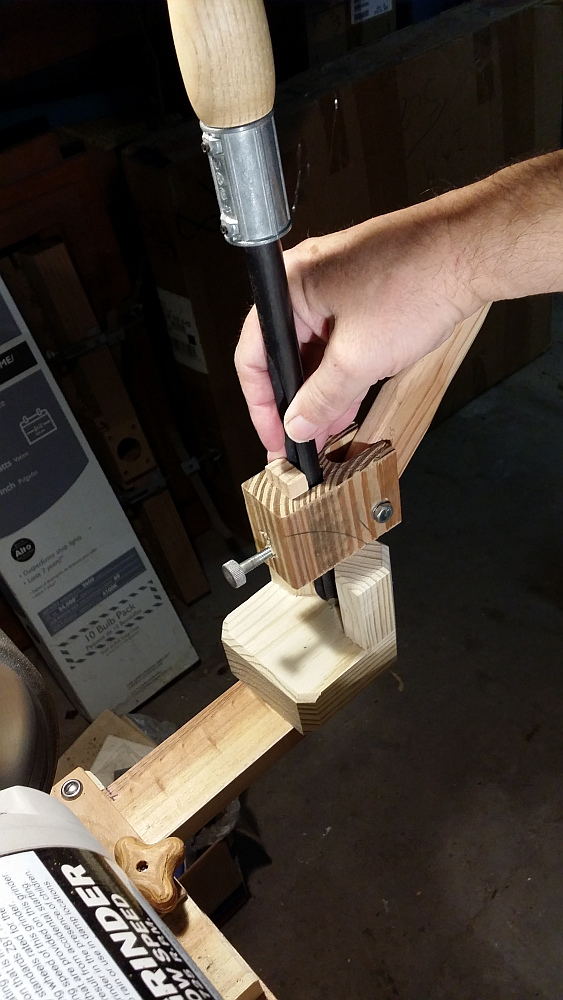
David Ellsworth designed a jig with a clamp block to hold the tool plus an adjustable arm that offsets the axis of rotation so that it can transition from the steep angle when held upright to the shallow angle when rotated to either side. It's simple and precise... move the pocket in and out to set the bevel on the side of the tool, and change the angle on the pivot post of the jig to adjust the front angle... rotating the jig from side to side does the rest. (see safety note at the end of this section).
Fortunately, I had already constructed one of these a few months ago. I was using it with a temporary pocket arm that was a lot cruder than the one I just made, but the jig itself worked just fine so I figured I'd stick with it for now. All I did to improve things was to make 2" tall sides on the pocket ... since that was how much the tool edge was supposed to protrude from the guide, I could just use that as a gauge when clamping the tool in the block. Works great ... stand the tool up in the pocket, drop the guide block down to the top of the pocket, tighten the clamp... you don't have to keep a ruler around and you don't need three hands to position the tool in the guide.
In the interest of safety, I'd like to suggest a few precautions in the use of the compound jig (or any jig for that matter). Due to the geometry of the tool edge and jig, combined with the aggressive cutting action of some wheels, it's possible for the edge to catch. Such a catch can force the jig and tool down, and when the tool meets resistance from the rear (in this case, the pocket) it can sometimes result in damage or outright destruction of the wheel and possibly injury to the operator. When I first started turning, I had just such a catch ... the wheel didn't shatter but it did scare the hell out of me. After trying to understand how it happened, and discussing it with more experienced turners, I came up with a series of precautions that I strictly adhere to.
· First off, I stay away from excessively steep angles ... lots of guys seem to be taking these tools up to 70 degrees to reach the bottoms of deep forms but I'm keeping mine at 60 or less which ensures that they stay a reasonable distance above the wheel's centerline. Anything above 60 degrees should be sharpened by hand on a platform.
·
Always stand off to the side when grinding ... just as with the lathe, there is a "line of fire" that you need to avoid.
· Hold the jig from above so that if it goes it won't pull your hand down with it (in the above photo of the jig, I was trying to take a picture and hold the tool handle at the same time, this is NOT how I sharpen.
).
· It is essential to make sure the wheel is perfectly true ... these catches seem to occur most often "on the bounce" when using a wheel that's a bit off (and even CBN wheels can be off since cheap motor shafts aren't always machined to the same spec as the wheels).
· I only use this jig on the fine 220 wheel, which is way less "grabby" than a coarse wheel..
· I always grind from the outer edge (where the bevel angle is shallow) into the center, gently lifting off when just past the tool's centerline, then repeating on the other side. The catch I had happened when introducing the tool "nose first," which other turners assure me is poor practice.
The last project was the platform rests ... these would be more involved since they had to be very steady but also had to adjust in three directions (in/out, up/down and platform angle). Fortunately, Veritas had already designed a nice one so I didn't have to reinvent the wheel, I just had to beef up the design to accommodate my materials (wood instead of extruded aluminum). More scratching on the chalk board.
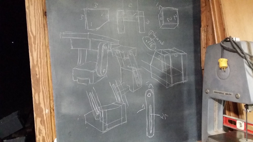
Wish I could thank the former owner of my house, the guy who decided it would be cool to mount a piece of billiard table slate on the inside of the shop door... it's been a real pleasure standing in front of it over the years holding a cup of coffee and a piece of chalk, working out designs that I could alter on the fly and recording measurements that I could read practically from across the room... every shop should have one of these. Unlike white boards and stinky old dry-erase markers, the chalkboard has a traditional warmth and charm that settles the mind.
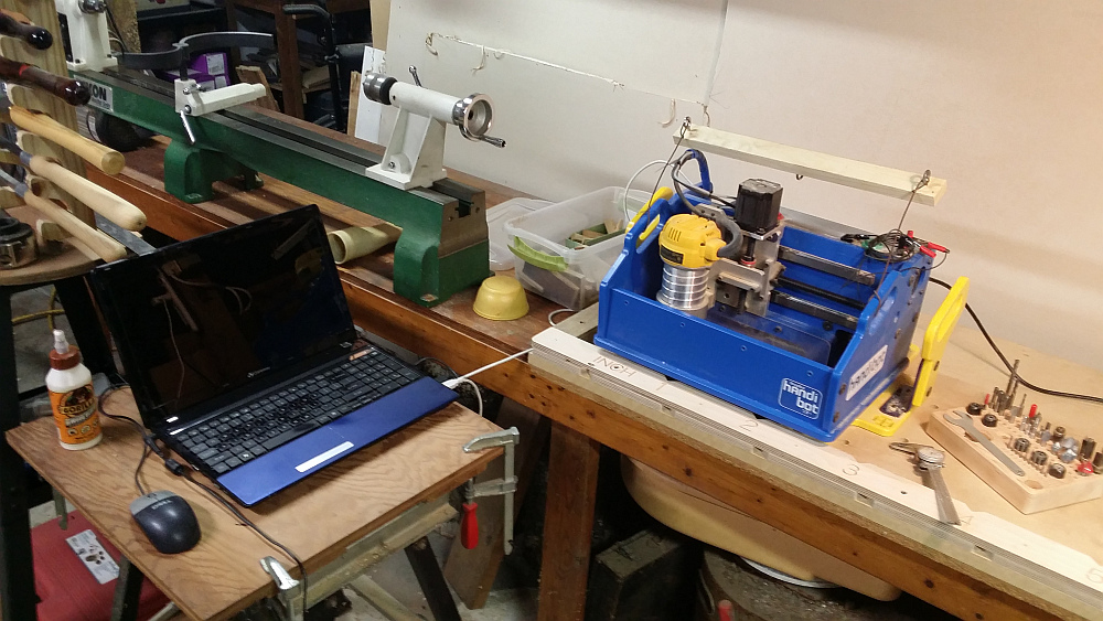
A CNC router called a "Handibot" along with its "brain" (my daughter's old laptop computer) are together becoming one of my favorite tools. I've had it about a year now, and while I got off to a slow start I'm finally moving beyond familiarization and experimentation to integrating it into the workflow. I'm still fascinated by it though ... one of the advantages of the tool is that you're supposed to be able to start it up and do something else while it's cutting, but I can't seem to do that just yet... I still sit and watch it move around like it's some sort of magical street theater.
Designing parts has always been a balancing act ... complexity, degree of precision required, the amount of time available to devote to hand work or machine setup, and so forth. Sometimes a design is dictated as much by the available tools and the available time as it is the maker's actual skills. To give a simple example, in the days before I had a plunge router I might have tried to avoid incorporating stopped slots into a design ... it would mean drilling a line of holes and cleaning out the waste with a chisel. Not that complex really, but it can be time consuming and a bit tedious if you have to do a bunch of them. But that same slot is a relatively easy operation on a router table... you do a plunge cut and slide the piece along the fence until the slot is the required length. Maybe clamp stops at either end if you're doing multiple cuts. Simple.
OK, but what if that slot has to be an arc or an S-shape? That might send you back to doing it by hand or crafting some sort of single-use jig to make the cut. A CNC router pretty much eliminates that ... just about any part that you can design on paper (well, in a CAD program) can be translated to machine code for the Handibot, which will then cut the piece, in any number you require and with positioning accuracy of something like 0.00025 (yeah, that's what they say, a quarter of a thousandth... about 6 microns or 1/14th the diameter of a human hair).
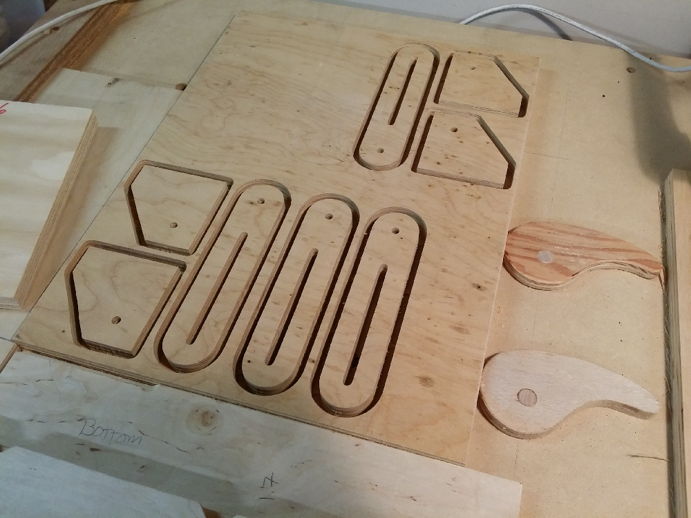
So when you need pieces with adjustment slots (which this tool rest happens to have), all you need to do is draw the design and the computer guides the router, cutting out all four of them in about the time it would have taken me just to measure and mark the wood and set up the clamp stops on my router table. And it also cut the sides that I needed from the same piece of wood... they aren't very complex pieces, all straight lines and a drilled hole, but still ... it was pretty cool to have all this done in one operation.
After I got the spacer blocks, pivot blocks and platform done, I assembled the whole thing with all-thread, nuts and washers. I was pretty pleased with the overall solidity and ease of adjustment.
But something was missing ... the tightening nuts weren't going to work, I mean who wants to have to keep reaching for a wrench? Wing nuts might do the trick but I always thought the common 1/4x20 wing nut was under-designed... if you have to crank them down fairly tight they kinda hurt your fingers because the wings are so small.
I could buy plastic knobs, but at three and a half bucks a pop (or more) that would add up (I needed twelve ... four for the bases, eight for the rests). Besides, after making the whole thing out of wood, who wants to add a bunch of plastic?
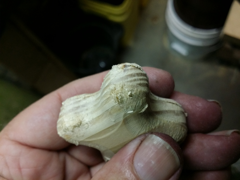
So, once again the Handibot came to the rescue. Design one, cut twelve...
_sm.jpg)
But wait, it wasn't nearly as easy as all that ... since this was a dual-sided design, I had to flip the wood over to cut the other side which meant there were some registration problems. While the Handibot can cut with almost microscopic accuracy, you also have to be accurate in your setup ... both the piece of wood itself, as well as the shims that clamp it in place, have to be perfectly cut (even to the point of compensating for the force of the clamps) because when you flip over the workpiece you are registering it to the opposing edge, which means any error you make cutting the piece is doubled. So when my shim was out by something like 0.016" and the workpiece was 8 1/32" instead of 8 inches ... the total error added up to a shift of about 3/32" or so. Frustrating.
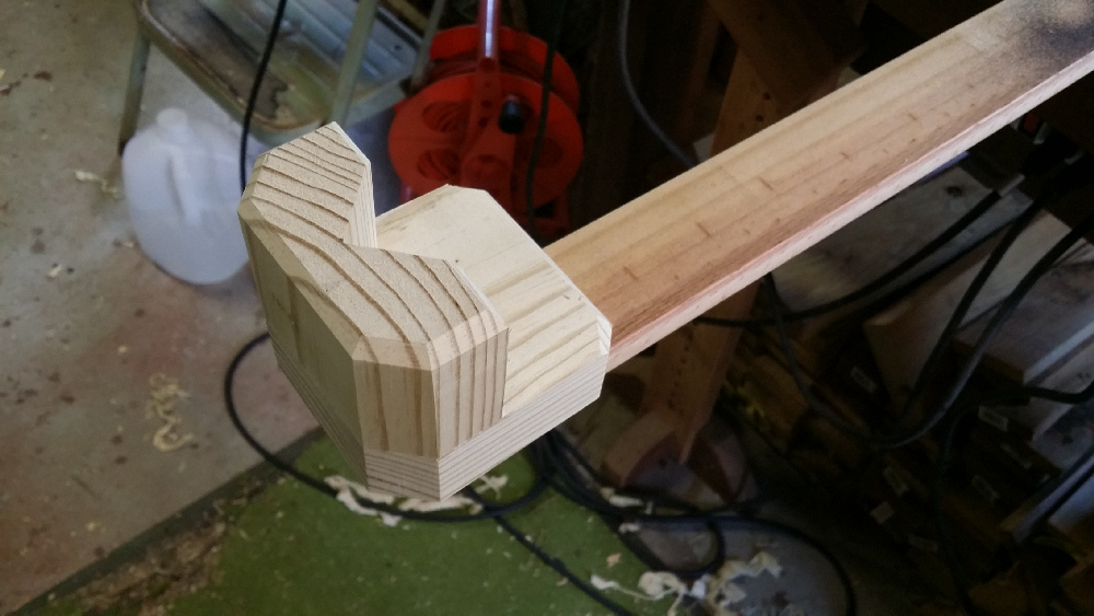
But fortunately, that shot above was taken AFTER a few trial cuts that allowed me to get all of this worked out ... below is an earlier test piece (my second try) in yellow pine scrap, which looks pretty ragged, but at least everything is lined up.
And so the router went on it's merry way...
_sm.jpg)
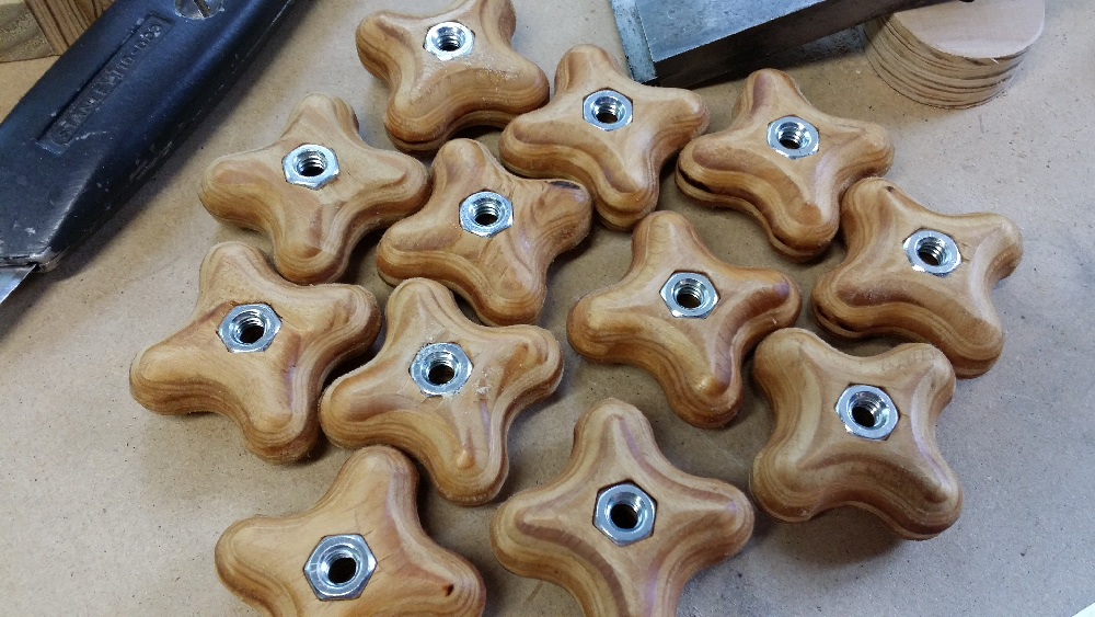
... after about fifteen minutes of cutting I had some nice wooden knobs.
_sm.jpg)
Then another twenty minutes of drum sanding, hammering the nuts in the pockets, and a little teak oil...
Next came the platforms on top. I made one out of 1/2" luan (below) but it didn't work out ... too old, too brittle, too soft.
So I looked around and found a scrap birch ply cabinet door that worked out much better...
_sm.jpg)
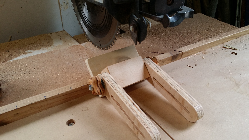
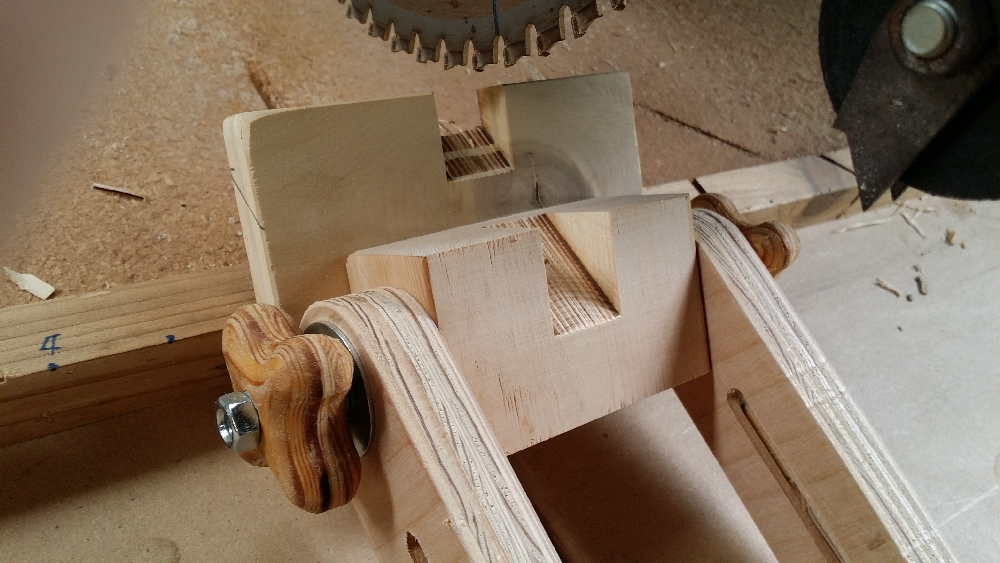
Once the platforms were attached, I remembered I had to cut some relief for the wheels on the underside of both the platform and the pivot block. I did the first one the old-school way, with a dovetail saw and chisel ... but then I realized that I could use those adjustment arms to hold the assembly at the proper angle and just cut the slot on the radial saw, which is what I did for the second one...
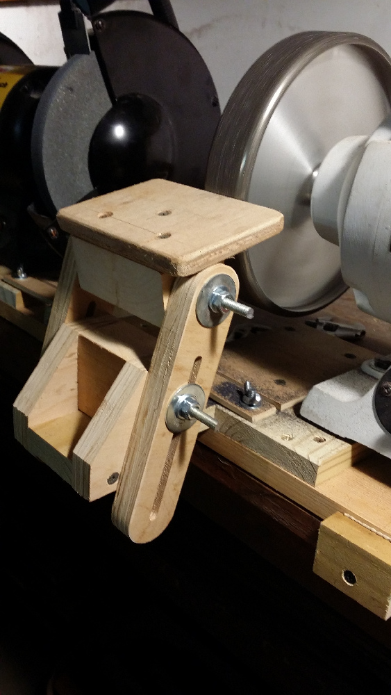
The final step was mounting the assembly to the bench. It would be nice to be able to move them when necessary so instead of screwing the bases down I set them on top of some of that thin non-slip shelf liner ... this would also help cut down on vibration. Then I made some small screw-on cleats for each side of the base and padded them with more shelf liner. Now they can't move horizontally but they can still be lifted out.
_sm.jpg)
_sm.jpg)
I guess that's about it ... sharpening should be a lot faster, easier and more precise, but in addition to that I'll have a little more versatility when it comes to fabricating parts... might even get around to making a knife from scratch, that's something I've been wanting to do for years.
But not just yet ... right now I've got to get to work on that bookcase for Sieren's room.
Photos: Samsung Galaxy Note 3.